As anyone who knows me will be only too aware, I’m something of an avid (read: obsessive) collector of vintage computing equipment. Some time ago, I was given the task of helping a widow out with a loft full of gear, which included several boxes of floppy disks and a rather nifty Dragon 64 in third-party dual-floppy housing which had belonged to her late husband. Since then, I’ve been gradually sorting through the collection to see what should be preserved for posterity and what should be recycled and came across something which should not only be preserved but shared.

First, some background: Des Critchlow, born 1940, was a man whose two passions were amateur radio and computing. Having upgraded from the Dragon 64 to an IBM Compatible, Des began keeping notes and logs on floppy disks both in service of his personal life and the radio network – RAYNET – to which he belonged. The following story is extracted from one of those disks, and something which I believe Des would have wanted to find a wider audience. The text has been corrected for typographical errors, but is otherwise duplicated intact.

Fact is often stranger than fiction.
Quite a few years ago when yours truly used an FT101EX a friend of mine, who we will call Rimmer, said can you do me a favour. He explained his son, a devout C.B.er on SSB was hoping to acquire a new rig for “DXing” with, and could I please test it out as it covered Ham bands as well as 27 MHz.
As I agreed, a date/time was suggested a few day later, and he duly arrived one evening. The rig turned out to be same as mine – an FT101EX modified to cover 27 MHz as well as all the Ham bands. After a few quick checks into a dummy load an antenna test was done. The set proved quite good and as at that time I was running a dipole on 20 metres I set out to get a report with it.
Tuning to a quite spot on 20 meters I was about to give a call, but I heard a weak and watery signal. The signal was a French maritime mobile asking for help from anyone who knew about engines or a fitter. By a stroke of luck the young man with me was a heavy goods fitter, and said he would help. We questioned the French station and gathered that his starter motor was sticking in, and so he could not get more than a few revs before horrible noises came from the engine. My young friend was most excited and insisted this was going to be dead easy. He said “tell him to shove it into second gear and rock it a bit and it should clear the problem.”
My friend could not understand why I just rolled about laughing. I said “don’t you understand you don’t tell anyone to rock a boat!!!” It took several minutes before an alternative method of clearing the problem was sent to the poor Frenchman. Which was, by the way, to belt the starter casing with a hammer. Lord knows who was listening, but they would have creased themselves if that message had been sent.
G3PTV

I recently became the owner of an HP ProLiant MicroServer N54L, a small box with a bunch of hard drive bays and a low-power AMD Turion dual-core processor. I’ve also been tweaking it quite heavily, resulting in a dramatic improvement in network performance and a significant drop in power draw – and this is how I did it. If you’re not running Linux, mind, everything past Step 1 is likely of no use to you.

Warning: The advice here worked for me, but some of it – in particular turning off journalling and using an aggressive spin-down profile on the drives – is hardly best-practice. It can even shorten the lifespan of certain components. Where something can have a deleterious effect, I’ll highlight it – but go into this warned that not everything I’ve done here is for everyone.

Step 1: Unlock the BIOS
The MicroServer is HP’s entry-level server, and as a result is missing several features of higher-end models – in particular hot-swap drive bays. This isn’t a physical restriction, but a fake restriction put in place by HP – and it can be removed by installing a modified BIOS. Doing so also allows all the SATA ports to run at 3Gb/s – two are limited to 1.5Gb/s by default – and fixes a flaw in the original BIOS that prevents the NIC from operating under certain operating systems.

HP has recently taken the decision to lock its BIOS updates behind a warranty wall: if you don’t have a warranty, you can’t get BIOS updates. That’s not very nice, so it’s a good job that someone has uploaded a pre-modified BIOS. The naughty person. Just download the file, write the image to a USB stick with dd (or ImageWriter if you’re on Windows) and power the server on with the stick in a port. Wait for the DOS prompt to appear and power off – you’re done.

Step 2: Network Tuning
Out of the box, I found the MicroServer’s network performance to be poor indeed under Ubuntu 13.10. Some of the blame has to go to the cheap Broadcom NIC, but I figured I could do better.

First, edit /etc/rc.local and stick the following lines into it, just above ‘exit 0’:

ethtool -G em1 rx 511
ifconfig em1 txqueuelen 1000
defaultroute=`ip route | grep "^default" | head -1`
ip route change $defaultroute initcwnd 10

This forces the NIC to use its entire ring buffer for RX packets – by default only 200 bytes of the 511 bytes available get used – and increases the transmit queue length to a figure better suited to gigabit network traffic. The default route is also tweaked.

Next, edit /etc/sysctl.conf and add the following:

fs.file-max = 100000
net.core.netdev_max_backlog = 50000
net.core.optmem_max = 40960
net.core.rmem_default = 16777216
net.core.rmem_max = 16777216
net.core.wmem_default = 16777216
net.core.wmem_max = 16777216
net.ipv4.conf.all.accept_redirects = 0
net.ipv4.conf.all.accept_source_route = 0
net.ipv4.conf.all.log_martians = 1
net.ipv4.conf.all.send_redirects = 0
net.ipv4.ip_local_port_range = 10000 65000
net.ipv4.tcp_fin_timeout = 10
net.ipv4.tcp_max_syn_backlog = 30000
net.ipv4.tcp_max_tw_buckets = 2000000
net.ipv4.tcp_rfc1337 = 1
net.ipv4.tcp_rmem = 4096 87380 16777216
net.ipv4.tcp_sack=0
net.ipv4.tcp_slow_start_after_idle = 0
net.ipv4.tcp_timestamps=0
net.ipv4.tcp_tw_reuse = 1
net.ipv4.tcp_wmem = 4096 65536 16777216
net.ipv4.udp_rmem_min = 8192
net.ipv4.udp_wmem_min = 8192
vm.swappiness = 10

A reboot will bring the box up with your new settings, or you can force a reload with sysctl -p (or sudo sysctl -p if you’re not root.) Combined, these two tweaks resulted in the throughout of the system going from about 40MB/s to 120MB/s, so it’s definitely worth doing.

Step 3: Power Tuning
The idle power of the MicroServer wasn’t great when I was finished tuning the network, pulling around 40W from the wall. A little careful tuning of the system, though, and that dropped to 21W – a significant saving.

First, we’ll discuss the fixes that won’t cause you any problems. Open /etc/rc.local again and add the following lines:

echo 'min_power' > '/sys/class/scsi_host/host2/link_power_management_policy'
echo 'min_power' > '/sys/class/scsi_host/host3/link_power_management_policy'
echo 'min_power' > '/sys/class/scsi_host/host4/link_power_management_policy'
echo 'min_power' > '/sys/class/scsi_host/host5/link_power_management_policy'
echo '0' > '/proc/sys/kernel/nmi_watchdog'
echo '1500' > '/proc/sys/vm/dirty_writeback_centisecs'
echo 'auto' > '/sys/bus/pci/devices/0000:00:18.3/power/control'
echo 'auto' > '/sys/bus/pci/devices/0000:00:00.0/power/control'
echo 'auto' > '/sys/bus/pci/devices/0000:00:01.0/power/control'
echo 'auto' > '/sys/bus/pci/devices/0000:00:06.0/power/control'
echo 'auto' > '/sys/bus/pci/devices/0000:01:05.0/power/control'
echo 'auto' > '/sys/bus/pci/devices/0000:00:11.0/power/control'
echo 'auto' > '/sys/bus/pci/devices/0000:00:12.0/power/control'
echo 'auto' > '/sys/bus/pci/devices/0000:00:13.0/power/control'
echo 'auto' > '/sys/bus/pci/devices/0000:00:13.2/power/control'
echo 'auto' > '/sys/bus/pci/devices/0000:00:18.4/power/control'
echo 'auto' > '/sys/bus/pci/devices/0000:00:12.2/power/control'
echo 'auto' > '/sys/bus/pci/devices/0000:00:18.2/power/control'
echo 'auto' > '/sys/bus/pci/devices/0000:00:14.0/power/control'
echo 'auto' > '/sys/bus/pci/devices/0000:00:14.1/power/control'
echo 'auto' > '/sys/bus/pci/devices/0000:00:14.3/power/control'
echo 'auto' > '/sys/bus/pci/devices/0000:00:14.4/power/control'
echo 'auto' > '/sys/bus/pci/devices/0000:00:16.0/power/control'
echo 'auto' > '/sys/bus/pci/devices/0000:00:16.2/power/control'
echo 'auto' > '/sys/bus/pci/devices/0000:00:18.0/power/control'
echo 'auto' > '/sys/bus/pci/devices/0000:00:18.1/power/control'
echo 'auto' > '/sys/bus/pci/devices/0000:02:00.0/power/control'

That’ll have a small but noticeable impact on power draw at idle, enabling a bunch of typically-off power management features. If you’ve got additional USB or PCIe devices in your MicroServer, you may find that this doesn’t catch all of ’em; install PowerTOP and go to the ‘Tunables’ tab to see if there’s anything labelled ‘Bad,’ then toggle it to ‘Good.’

That’s a start, but for real savings we need to spin the drives down. This may or may not be possible in your usage scenario: mechanical drives have a limited number of load/unload cycles before they break, and the last thing you want to be doing is having it constantly spinning down and spinning back up again. Because I’m not always accessing the MicroServer – I back up to it once a day, stream media from it during the evening, and otherwise mostly leave it alone – I can get away with a reasonably aggressive power-saving plan; you may well need to adjust the numbers below to suit your own needs.

If you want to continue, start with adding the following to /etc/rc.local:

hdparm -S 60 /dev/sda /dev/sdb /dev/sdc /dev/sdd
hdparm -B 1 /dev/sdb /dev/sdc /dev/sdd
hdparm -M 128 /dev/sdb /dev/sdc /dev/sdd

That tells the system to spin all four hard drives down after 300 seconds of inactivity. If you ain’t got four hard drives, edit the line accordingly. Some drives may not sleep on their own; if that’s the case, have a look at the Powernap tool and use it in conjunction with ‘hdparm -y’ to force a drive to spin down. I use it on my system because one drive of a mirror sleeps while the other stays awake; Powernap watches for this, and when the first drive sleeps it forces the second into the low-power state.

The second command puts the drives in the most aggressive power management level possible, while the third puts it into the quietest possible acoustic management mode. Note that I haven’t included the boot drive sda there: the drive that came with my MicroServer doesn’t support either of those settings. Try running the command yourself, and if your drives do support it then add them to the above list.

One drive that won’t spin down is your boot drive – in my case, the 250GB drive the MicroServer came with. If that’s a problem, consider switching to a solid-state drive (SSD) instead. If you’re truly desperate to save as much power as possible but have no cash left, however, there are options. First, move /var – the bit of the disk that sees the most activity, in particular due to the log files held in /var/log, to a spare USB flash drive you’ve got lying around. You’ll need at least 1GB, preferably 2GB or more to allow for sudden growth.

The procedure for moving /var isn’t straightforward, and is rife with danger – it’s perfectly possible to end up with a non-booting system. If you’re still reading, here’s how I did it (as root) with the USB stick inserted as /dev/sde. First, edit /etc/fstab and insert a line to mount the USB stick as /var, and while you’re at it edit the root mount point to disable access time writing.

/dev/sde1       /var    ext4    defaults,noatime,nodiratime     0       1
/dev/sda1       /       ext4    noatime,nodiratime,errors=remount-ro 0       1

I’d recommend using the drive’s UUID (visible with the blkid command) instead of the device node, ‘cos you don’t want the system to get confused and mount the wrong drive. Next, populate the drive:

mkfs.ext4 /dev/sde1
mkdir /tempvar
mount -t ext4 /dev/sde1 /tempvar
cp -rfp /var -T /tempvar
umount /tempvar
mount /dev/sde1 /var
reboot

When the server comes up – assuming nothing went wrong – /var is now running from the USB drive, saving writes to the mechanical drive. However, you may find the mechanical drive still doesn’t spin down. In my case, this was ‘cos I was running a journalling file system – ext4 – which was always writing data to the disk. Simple fix: turn journalling off.

Another warning: turning journalling off is a really bad idea. Journalling is there to ensure that the file system doesn’t get corrupted. Turn it off, and there’s a non-zero chance that a sudden reboot – a power-cut, say – will result in a corrupt root file system and a non-booting server. I’ve got a UPS and a backup of the file system, so it’s a chance I’m willing to take – but consider the implications long and hard before continuing.

If you’re still convinced you want to do this, you can turn ext4’s journalling option off by remounting the root filesystem read-only and issuing the following command:

tune2fs -O "^has_journal" /dev/sda1

With that, the root drive is now free to spin down – resulting in the aforementioned 21W idle power draw. But seriously, don’t do this. Just buy a cheap SSD instead.

During a discussion on a web forum, I put forward the claim that for heavy usage scenarios buying a power supply that delivers twice the wattage required can add up to energy savings. This was brought into question, so I devised a neat little spreadsheet with three simulated scenarios – the result of which I have reproduced below.

Using several assumptions, I built three models: a gamer who plays two hours a day, a pro-gamer who plays eight hours a day, and a folder or miner who has the system fully loaded 24 hours a day. Each of these users is building a new rig, the specifications of which are given below. In all three cases, it’s a completely new rig: no existing parts are being used. The models compare the energy used by two otherwise identical power supplies, one of which is running at at near-full-load and the other one at half-load – and compare the energy savings that come from the fact that PSUs are naturally more efficient at 50% load. Actual figures for this increase in efficiency, taken from the official 80 PLUS certification requirements, can be found in the Assumptions section.

THE RIG

  • Radeon R9 290(X) TDP: 300W
  • Intel Core i7 4770K TDP: 84W
  • Motherboard, Fans and So Forth: 40W
  • Non-Green Hard Drive: 8W active, 3W idle
  • Total maximum system power draw: 432W.

ASSUMPTIONS
When gaming, the GPU is 100% loaded and the processor 60% loaded (two cores versus all four cores, plus overhead), while the hard drive is mostly idle for a total power draw of 393.4W rounded down to 393W for simplicity’s sake.
When participating in distributed computing projects like Folding@Home or Litecoin mining, both CPU and GPU are 100% loaded, while the hard drive is mostly idle for a total power draw of 428W.
Electricity currently costs on average 15.32p per kilowatt hour (KWh), based on figures from the Energy Saving Trust. From the same page, generating each KWh of electricity causes 0.517kg of carbon dioxide to be emitted into the atmosphere.
The cost of electricity is rising at 7 per cent annually, based on an average of the most recent price rises listed on USwitch.
The PSUs in question have a five-year warranty, and thus five-year worst-case lifespan. All calculations, therefore, are based over a five-year period.
The two PSUs under comparison are both 80 PLUS Titanium rated, one at 450W and one at 900W. As a result, at the system’s peak load the 450W offers 91 per cent efficiency, and the 900W offers 96 per cent efficiency – both minimum efficiency figures at 100% and 50% load respectively as required by the 80 PLUS certification. Buying the 900W PSU costs £50 more than the 450W PSU.

With that in mind, let’s run the numbers.

The Gamer
The gamer works in an office all day, during which time his or her PC at home is powered off. On average, the gamer manages to get in around two hours of gaming every day – some days there’s no gaming at all, but on a weekend it might be an eight-hour marathon. At all other times, the computer is switched off or in an extremely low power mode.

Result of Simulation:
Over a five-year period, paying the extra £50 for the 900W PSU will have cost the user £36. In other words, this use-case makes no financial sense. Additionally, however, the move will have reduced the environmental impact of the PC by preventing the emission of 8.49kg of carbon dioxide into the atmosphere.

The Pro-Gamer
The pro-gamer works at gaming all day. Eight hours a day, seven days a week he or she is hammering the system, honing skills and pwning the opposition. Outside the ‘office hours,’ the PC is switched off or in an extremely low power mode.

Result of Simulation:
Over a five-year period, paying the extra £50 for the 900W PSU will have saved the user £8. Not much, but it is a saving. Additionally, the move will have reduced the environmental impact of the PC by preventing the emission of 33.96kg of carbon dioxide into the atmosphere.

The Folder
This user has their system forming part of a distributed computing cluster. Perhaps they’re running Folding@Home or BOINC for scientific research, or renting their system out as a renderfarm, cracking passwords and generating rainbow tables, or perhaps they’re trying to mint the latest cryptocurrency. Whatever the reason, the system is at full load – CPU and GPU – all day, every day. Hey, on the plus side: at least their room is nice and warm.

Result of Simulation:
Over a five-year period, paying the extra £50 for the 900W PSU will have saved the user £139. Hey, that’s enough to buy a replacement PSU! Additionally, the move will have reduced the environmental impact of the PC by preventing the emission of 110.94kg of carbon dioxide into the atmosphere.

CONCLUSIONS
If you only load your PC for a couple of hours a day, don’t bother speccing it with a PSU capable of delivering double your wattage requirement. You’ll never recoup your investment, and the environmental impact is minimal. If you’re a pro-gamer, it could be worth doing – especially as you’ll be able to claim the cash spent on the PSU as a business expense against tax, something I didn’t take into account in my calculations. If you’re a folder, though, absolutely go for maximum efficiency – it has a real-world environmental benefit and gives you the cash you’d need to replace said PSU once it’s out of warranty. Win-win!

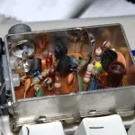
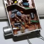
Helping out a friend with a picture or two of the Astec UM1233 RF Modulator’s inner workings. If you’re curious, it’s a device which was incredibly popular in the 80s and 90s in home computers, and takes video and audio as an input and turns them into either VHF or UHF (depending on country) radiofrequency signals – the same signals as analogue TV tuners expect to receive. If you crack open a ZX80, ZX81, Spectrum of almost any model, Commodore 64, ORIC, Newbrain, Dragon – almost any 80s microcomputer aimed at the home market – you’ll probably find one of these.

The Burnduino Kit
The Burnduino Kit

The Burnduino Kit

The Burnduino Shield is, as the name suggests, an add-on ‘shield’ for the Arduino microcontroller and compatibles. It’s designed to make programming an ATmega328 DIP-package microcontroller easier, and turns the Arduino into a remarkably efficient AVR programmer. Features include:

  • 28-pin universal ZIF (zero insertion force) socket, meaning no bent pins and fast chip change
  • Supports uploading of 16MHz external crystal and 8MHz internal oscillator Arduino bootloaders onto bare ATmega microcontrollers
  • Fully supported within the Arduino IDE software
  • Allows uploading of bootloaders and sketches from a single shield
  • Mode select jumpers mean no rewiring – ever
  • Saves money: buy unprogrammed ATmega328 chips and burn the bootloader yourself

The Burnduino is provided as a kit, which contains the printed circuit board, a high-quality 28-pin locking ZIF socket made by 3M, a 16MHz crystal with two 22pF decoupling capacitors, a 10KOhm pull-up resistor for the reset line, male 2.54mm headers and three 2.54mm jumpers for the mode select pins. All components are through-hole and easy to solder, even for a novice.

The Burnduino’s mode select jumpers allow a single shield to perform two tasks: when in ‘BTLDR’ mode, with the RX and TX jumpers open, the Burnduino works with an Arduino and the Arduino-as-ISP sketch to burn new bootloaders onto blank or pre-used ATmega microcontrollers. Close the RX and TX jumpers and move the mode select jumper to ‘SKETCH’ and the Burnduino allows the Arduino IDE to upload sketches to bootloader-equipped ATmegas.

Bootloader Mode

  1. Upload the ‘ArduinoISP’ sketch (File – Examples) from the Arduino IDE to your Arduino or compatible board.
  2. Connect the Burnduino shield.
  3. Set the lower-left Mode Select jumper to BTLDR, shorting the middle and top pins.
  4. Remove the jumpers from the RX and TX pins.
  5. Insert your ATmega microcontroller into the ZIF socket
  6. Select your chosen board type from the Tools – Board menu in the Arduino IDE.
  7. Upload the bootloader using Tools – Burn Bootloader – w/ Arduino as ISP.
  8. To program another ATmega, simply replace the chip in the socket and burn the bootloader again.

Sketch Mode

  1. Remove the ATmega chip from your Arduino board and put it somewhere safe.
  2. Connect the Burnduino shield.
  3. Set the lower-left Mode Select jumper to SKETCH, shorting the middle and bottom pins.
  4. Short the RX and TX pins with the jumpers provided.
  5. Select the bootloader type from the Tools – Board menu in the Arduino IDE.
  6. Insert your bootloader-equipped ATmega chip into the ZIF socket.
  7. Load your sketch into the Arduino IDE and hit the upload button.
  8. To upload the sketch to a new chip, simply replace the chip in the ZIF socket and hit the upload button again.

If you want to take advantage of the ATmega’s internal oscillator, which means your finished design can ditch the 16MHz crystal and decoupling capacitors to save money and space, you’ll need to follow the ‘Minimal Circuit’ instructions from the Arduino to Breadboard article to add a new board definition to the Arduino IDE. If you need to upload bootloaders to ATmega328-PU chips – rather than the more common ATmega328P-PU – follow these instructions.

NOTE: The Burnduino uses the ArduinoISP sketch to upload a bootloader to the chip in the ZIF socket. This sketch, at present, does not support the new Arduino Uno, which uses different USB circuitry. If you want to use the Burnduino as an ISP, you’ll need to have an Arduino Duemilanove or third-party compatible with FTDI circuitry instead.

Arduino Burner PCB

Arduino Burner PCBContinuing my creation of circuits that save me a little time, I’ve developed a shield which turns an Arduino Duemilanove (or compatible) into an EPROM burner for ATMega328 chips. Imaginative as ever, I call it the “Arduino Burner.”

While working on the Standalone Sleepduino, I had cause to burn a custom bootloader to an ATMega328 chip in order to convince it to use its internal 8MHz oscillator instead of an external 16MHz crystal. With an Arduino Duemilanove, that’s not too difficult: follow the instructions from the Arduino To Breadboard article and you’re away.

It does, however, require a bit of time to set up the various wires; then more time is required moving the wires to upload a sketch to the newly-created Arduino-compatible microcontroller. Not much time, to be fair, but time nevertheless. So, the Arduino Burner was born.

The Arduino Burner is a simple shield based on the wiring from the Arduino To Breadboard article. It features room for a 16MHz crystal and decoupling capacitors, although these can be safely ignored if you’re programming an ATMega using the 8MHz breadboard bootloader. Installing them does, however, mean that you have the choice of flashing either bootloader; leaving the holes unpopulated means that you’ll be limited to the 8MHz version only. There’s also a 10K pullup resistor for the reset line, although again this is a ‘nice to have’ that can be ignored.

Usage is simple: stick a raw ATMega328 into the zero insertion force (ZIF) socket in the middle of the shield, set J1 to ‘BTLDR’ and open the RX and TX jumpers and you can burn a bootloader straight from the Arduino IDE. When your bootloader is installed, you can close the RX and TX jumpers and switch J1 to ‘SKETCH’ to upload a sketch – but remember to remove the Arduino’s own ATMega, or you’ll be uploading the sketch to that instead of your new chip!

The ZIF socket means that the legs of the ATMega328 are protected from damage – a key point if you’re burning large quantities of chips. It does, however, increase the cost of the shield quite significantly: a single 28W DIP socket is around 20p, while the particular low-profile ZIF chosen for this shield is around £8 – although this does drop as you buy quantities.

If you’re only creating one-off standalone projects, the Arduino Burner shield is overkill. If you’re doing large quantities and don’t fancy shelling out for a real AVR, however, it can be a serious time-saver.

I’ll be getting a prototype made up towards the end of the month, so pop back then if you want to see the shield in action.

Standalone Sleepduino Working

Just a quick update on the Sleepduino project: the PCBs for the Sleepduino Shield and Standalone Sleepduino arrived from the fab yesterday, and they work a treat.

Here’s a quick comparison between the Standalone Sleepduino and its breadboarded prototype:

Sleepduino Standalone Final/Prototype Comparison

As you can see, the Standalone Sleepduino is pretty compact, but still packs all the features of the original Arduino-powered version. In fact, it’s possible to take the (socketed) microcontroller out of the Sleepduino and upload a revised sketch, if you’ve got an ATtiny or similar or a spare Arduino to do the programming.

Just in case you doubt it works:

Standalone Sleepduino Working

At some point, I’ll be making a few tweaks to the design and then exporting some Gerbers for mass-production. Once I’ve got a costing for the PCB fabrication and parts – a 10K poteniometer, piezoelectric buzzer, three RGB LEDs, three buttons, nine 270-Ohm resistors and an ATMega-328 with socket – I’ll have a better idea of whether the project is worth pursuing.

Arduino Duemilanove Side View

Arduino Duemilanove Side ViewIn the course of the design for the Standalone Sleepduino, I needed to create a bare-bones breadboard that could run an Arduino sketch. I really mean bare bones, too: I didn’t even want to include the 16MHz crystal, as through-hole versions take up too much room and surface-mount versions are a pain (as I found when I got hold of a pair of Texas Instruments LaunchPads, but I digress.)

I snagged myself an ‘Arduino compatible component kit‘ from the lovely guys at Oomlout, which included all the parts I didn’t really need but wanted on hand just in case alongside the most important part of the kit: the ATMega328 microcontroller itself.

Sticking it in a breadboard, I followed the official instructions on how to burn an Arduino bootloader onto an ATMega328 so that it uses its internal 8MHz oscillator instead of an external crystal as its clock source.

At least, I tried to.

I spent about an hour wrestling with one major problem:

avrdude: Expected signature for ATMEGA328P is 1E 95 0F
Double check chip, or use -F to override this check.

Every single time I tried to program the 8MHz bootloader, avrdude told me to -F off. Eventually, I twigged what was going on: official Arduinos have an ATMega328P-PU chip, which you can see printed on top. In good light. If you squint a bit. My chip?

An ATMega328-PU.

One little letter, so much heartache. While the ATMega328P and ATMega328 microcontrollers are pretty much interchangeable, they have different signatures. The version of avrdude that ships with the Arduino IDE knows about ATMega328Ps, but not about ATMega328s. Hence my problem.

Thankfully, there’s a fix. To load an Arduino bootloader onto an ATMega328, open up avrdude.conf (found in /usr/share/arduino/hardware/tools/ on Linux boxes) and search for the string “0x1e 0x95 0x0F”. That’s the signature of an ATMega328P. Replace it with “0x1e 0x95 0x14”, which is the string of an ATMega328 and save the file. If you’re on Linux, you’ll need to be root to save the file. Restart the Arduino IDE, and you should be able to burn the bootloader without any errors.

When you’re done, remember to replace “0x1e 0x95 0x14” with “0x1e 0x95 0x0F” again, or you’ll get a bunch of messages telling you that only assembler is supported…

UPDATE: While this all still works, compiling sketches for the thing is broken as of Arduino 1.0.0. To fix, you need to copy a file into a certain directory. On Linux, it’s a case of:

sudo cp /usr/share/arduino/hardware/arduino/variants/standard/pins_arduino.h /usr/share/arduino/hardware/arduino/cores/arduino/

That should fire things back into life.

Standalone Sleepduino PCB

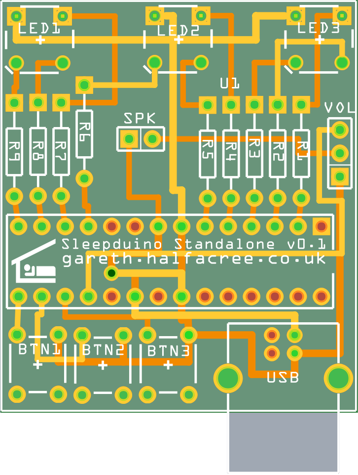
Standalone Sleepduino PCBMy original concept to create the Sleepduino as an Arduino shield to aid with sleep via white-noise and night-lights – or as a convenient way of getting three RGB LEDs, three buttons and peizoelectric buzzer with adjustable volume into an Arduino – is good, but wouldn’t a stand-alone version be better?

Yes. Yes, it would.

As a result, my order with the fab now includes an original Sleepduino shield along with the new design: the Standalone Sleepduino. Measuring a mere 17.6cm², it’s half the size of the Sleepduino shield. It’s not just a reduced footprint, though: as the name suggests, the Standalone Sleepduino no longer requires an Arduino to operate, shaving about £22 off the cost of the device for those who don’t already have an Arduino or compatible hanging around.

How? By taking the chip at the heart of the Arduino, the ATMega328 microcontroller, and embedding it directly into the middle of the circuit board.

To keep the size down and reduce the number of components required, the design of the Standalone includes a few tweaks over a traditional standalone Arduino creation. First of all, the traditional 16MHz crystal and associated capacitors aren’t there: the Sleepduino doesn’t need an accurate clock to work, so I’m using the 8MHz oscillator built in to the ATMega328 instead. There’s also no sign of a 5V regulator: instead, a USB B socket provides connectivity to a PC USB port or USB-based charger, which already provides a regulated 5V feed.

The Standalone Sleepduino won’t be for everyone: while it’s technically possible to reprogram it in the same way as the newly-renamed Sleepduino Shield, it involves having an existing Arduino or AVR programmer and taking the microcontroller off the board. If you’re looking for something to hack, the Sleepduino Shield will still be the better option; that goes doubly if you’ve already got an Arduino.

For those who just want a combination nightlight – with 334 possible colour combinations and four brightness settings, no less – and white-noise generator, however, the Standalone Sleepduino should prove a winner.

If I get enough interest, I’ll be sending off for a batch of both Standalone Sleepduinos and Sleepduino Shields from a PCB fab in China. I’ll then make them available either as a kit, or pre-assembled if you don’t fancy soldering it up yourself. Once my prototypes arrive, I’ll be doing some demonstration videos too.

Standalone Sleepduino BreadboardOh, and if you’re wondering how the Standalone Sleepduino looks when it’s not in its lovely compact PCB form, here’s the breadboarded prototype:

Not quite so pretty, huh?

Back-of-the-envelope calculations suggest that it’ll cost me around £13 to produce each Sleepduino Standalone kit, plus a quid or so for a USB A-B cable to go with it.

If you’d like to register interest in snagging yourself a kit or pre-made Sleepduino, drop me a line.

Sleepduino PCB

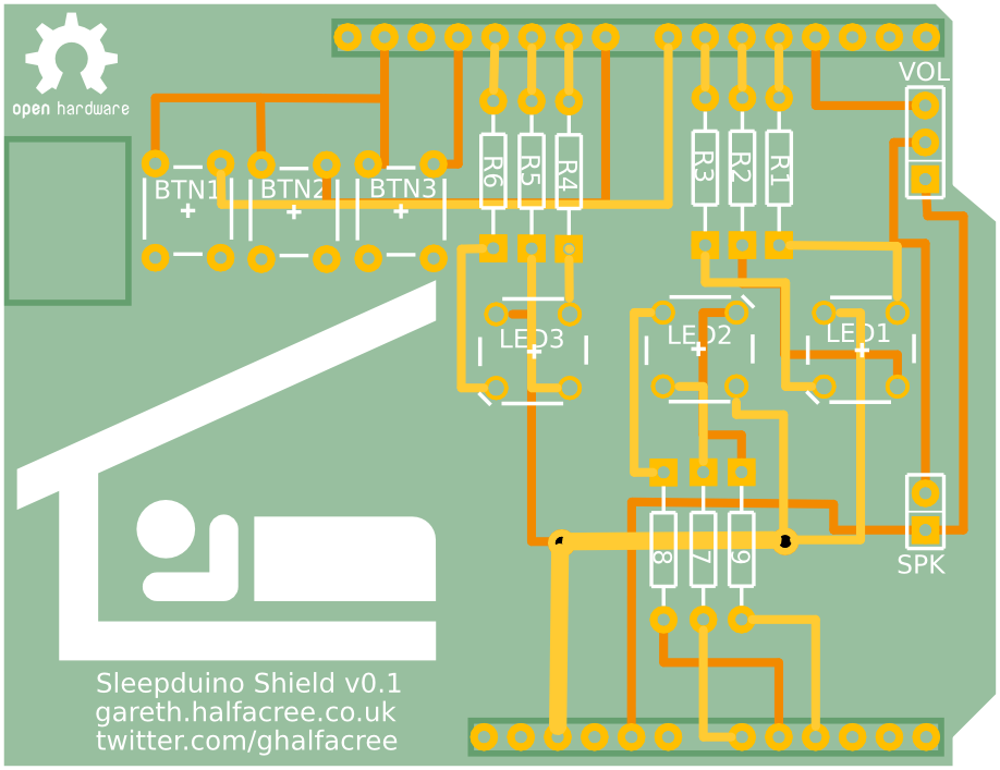
Sleepduino PCBAs a new father, I’ve found it’s difficult to convince my little bundle of noise to go to sleep at night. A common method of convincing a baby to sleep is to provide ‘white noise,’ either through the use of an expensive specialist baby-soother or by detuning a radio. Alternatively, there’s the Sleepduino.

Because I value my sleep more than I value my free time, I spent an afternoon designing and coding an combination white noise generator and nightlight for Alice’s nursery. Thankfully, I had the components I needed lying around: an Arduino with breadboard, three RGB LEDs, three tactile buttons, a piezoelectric buzzer and a potentiometer. Plus a whole mess of wiring.

The buttons control the LEDs: each LED has its own button, which cycles it through seven different colours before turning it off. Press the button again, and it’ll switch on again. The pot controls the volume of the buzzer, which exists to vocalise the output of a pseudorandom bit-shift register to generate a pleasing ‘static’ sound.

Set the LEDs to provide whatever level and colour of nightlight you think your baby – or, indeed, you – would prefer, adjust the volume of the white noise (apparently, it should be around the same volume as being in the same room as someone taking a shower) and cross your fingers that you’re going to enjoy the best night of sleep you’ve ever had.

It’s only the second proper night of using it, but it seems to be working: Alice had the best night’s sleep she’s ever had last night, and she’s been settled for a good couple of hours now without issue.

I’ve designed a printed circuit board version of the Sleepduino which plugs into the top of the Arduino without all the distracting and easily-knocked wiring. I’m making an initial prototype, which will arrive from the fab towards the end of the month. If it works, I’ll be opening the floor for anyone who wants to buy one.

Be aware, however: this is an Open Hardware project. I’m making the source code (most of which is appropriated from other projects anyway), schematics and PCB layout available under a Creative Commons Attribution-NonCommercial-ShareAlike licence, meaning you don’t have to buy one from me. If you’d rather, you can just grab the files and make one yourself. I won’t stop you. Hell, I’m actively encouraging it.

The pre-built shields will be for people who don’t fancy building one themselves, and I’ll probably also make them available with Arduino clones underneath so they’re literally ready to go out of the box.

Hopefully you guys will find them as useful as I’ve found the prototype version.