Arduino Burner PCB

Arduino Burner PCBContinuing my creation of circuits that save me a little time, I’ve developed a shield which turns an Arduino Duemilanove (or compatible) into an EPROM burner for ATMega328 chips. Imaginative as ever, I call it the “Arduino Burner.”

While working on the Standalone Sleepduino, I had cause to burn a custom bootloader to an ATMega328 chip in order to convince it to use its internal 8MHz oscillator instead of an external 16MHz crystal. With an Arduino Duemilanove, that’s not too difficult: follow the instructions from the Arduino To Breadboard article and you’re away.

It does, however, require a bit of time to set up the various wires; then more time is required moving the wires to upload a sketch to the newly-created Arduino-compatible microcontroller. Not much time, to be fair, but time nevertheless. So, the Arduino Burner was born.

The Arduino Burner is a simple shield based on the wiring from the Arduino To Breadboard article. It features room for a 16MHz crystal and decoupling capacitors, although these can be safely ignored if you’re programming an ATMega using the 8MHz breadboard bootloader. Installing them does, however, mean that you have the choice of flashing either bootloader; leaving the holes unpopulated means that you’ll be limited to the 8MHz version only. There’s also a 10K pullup resistor for the reset line, although again this is a ‘nice to have’ that can be ignored.

Usage is simple: stick a raw ATMega328 into the zero insertion force (ZIF) socket in the middle of the shield, set J1 to ‘BTLDR’ and open the RX and TX jumpers and you can burn a bootloader straight from the Arduino IDE. When your bootloader is installed, you can close the RX and TX jumpers and switch J1 to ‘SKETCH’ to upload a sketch – but remember to remove the Arduino’s own ATMega, or you’ll be uploading the sketch to that instead of your new chip!

The ZIF socket means that the legs of the ATMega328 are protected from damage – a key point if you’re burning large quantities of chips. It does, however, increase the cost of the shield quite significantly: a single 28W DIP socket is around 20p, while the particular low-profile ZIF chosen for this shield is around £8 – although this does drop as you buy quantities.

If you’re only creating one-off standalone projects, the Arduino Burner shield is overkill. If you’re doing large quantities and don’t fancy shelling out for a real AVR, however, it can be a serious time-saver.

I’ll be getting a prototype made up towards the end of the month, so pop back then if you want to see the shield in action.

Standalone Sleepduino Working

Just a quick update on the Sleepduino project: the PCBs for the Sleepduino Shield and Standalone Sleepduino arrived from the fab yesterday, and they work a treat.

Here’s a quick comparison between the Standalone Sleepduino and its breadboarded prototype:

Sleepduino Standalone Final/Prototype Comparison

As you can see, the Standalone Sleepduino is pretty compact, but still packs all the features of the original Arduino-powered version. In fact, it’s possible to take the (socketed) microcontroller out of the Sleepduino and upload a revised sketch, if you’ve got an ATtiny or similar or a spare Arduino to do the programming.

Just in case you doubt it works:

Standalone Sleepduino Working

At some point, I’ll be making a few tweaks to the design and then exporting some Gerbers for mass-production. Once I’ve got a costing for the PCB fabrication and parts – a 10K poteniometer, piezoelectric buzzer, three RGB LEDs, three buttons, nine 270-Ohm resistors and an ATMega-328 with socket – I’ll have a better idea of whether the project is worth pursuing.

Arduino Duemilanove Side View

Arduino Duemilanove Side ViewIn the course of the design for the Standalone Sleepduino, I needed to create a bare-bones breadboard that could run an Arduino sketch. I really mean bare bones, too: I didn’t even want to include the 16MHz crystal, as through-hole versions take up too much room and surface-mount versions are a pain (as I found when I got hold of a pair of Texas Instruments LaunchPads, but I digress.)

I snagged myself an ‘Arduino compatible component kit‘ from the lovely guys at Oomlout, which included all the parts I didn’t really need but wanted on hand just in case alongside the most important part of the kit: the ATMega328 microcontroller itself.

Sticking it in a breadboard, I followed the official instructions on how to burn an Arduino bootloader onto an ATMega328 so that it uses its internal 8MHz oscillator instead of an external crystal as its clock source.

At least, I tried to.

I spent about an hour wrestling with one major problem:

avrdude: Expected signature for ATMEGA328P is 1E 95 0F
Double check chip, or use -F to override this check.

Every single time I tried to program the 8MHz bootloader, avrdude told me to -F off. Eventually, I twigged what was going on: official Arduinos have an ATMega328P-PU chip, which you can see printed on top. In good light. If you squint a bit. My chip?

An ATMega328-PU.

One little letter, so much heartache. While the ATMega328P and ATMega328 microcontrollers are pretty much interchangeable, they have different signatures. The version of avrdude that ships with the Arduino IDE knows about ATMega328Ps, but not about ATMega328s. Hence my problem.

Thankfully, there’s a fix. To load an Arduino bootloader onto an ATMega328, open up avrdude.conf (found in /usr/share/arduino/hardware/tools/ on Linux boxes) and search for the string “0x1e 0x95 0x0F”. That’s the signature of an ATMega328P. Replace it with “0x1e 0x95 0x14”, which is the string of an ATMega328 and save the file. If you’re on Linux, you’ll need to be root to save the file. Restart the Arduino IDE, and you should be able to burn the bootloader without any errors.

When you’re done, remember to replace “0x1e 0x95 0x14” with “0x1e 0x95 0x0F” again, or you’ll get a bunch of messages telling you that only assembler is supported…

UPDATE: While this all still works, compiling sketches for the thing is broken as of Arduino 1.0.0. To fix, you need to copy a file into a certain directory. On Linux, it’s a case of:

sudo cp /usr/share/arduino/hardware/arduino/variants/standard/pins_arduino.h /usr/share/arduino/hardware/arduino/cores/arduino/

That should fire things back into life.

Standalone Sleepduino PCB

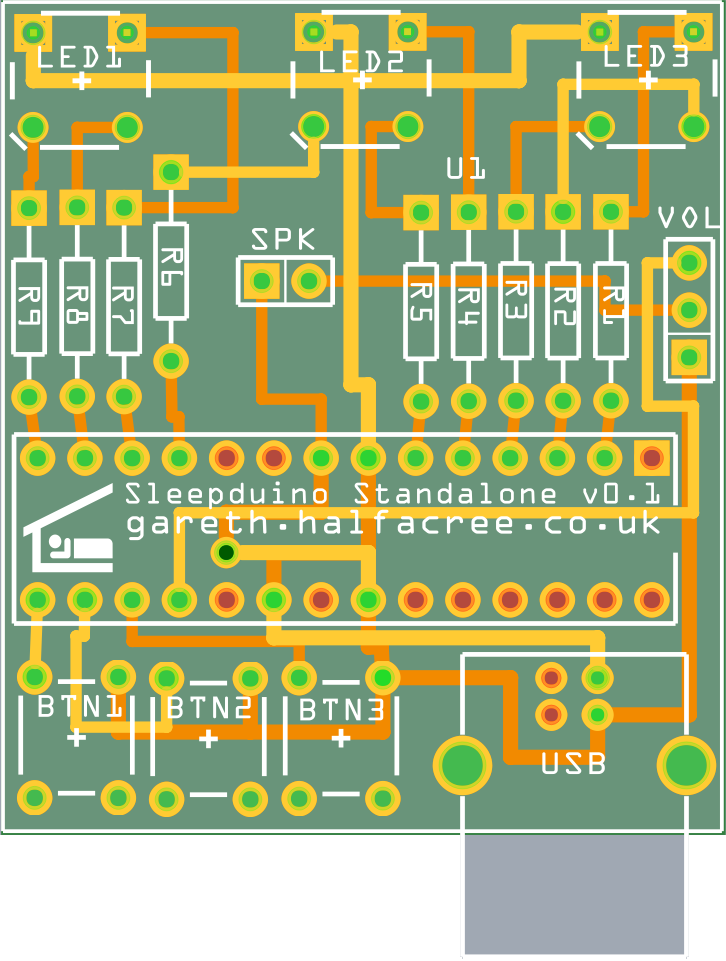
Standalone Sleepduino PCBMy original concept to create the Sleepduino as an Arduino shield to aid with sleep via white-noise and night-lights – or as a convenient way of getting three RGB LEDs, three buttons and peizoelectric buzzer with adjustable volume into an Arduino – is good, but wouldn’t a stand-alone version be better?

Yes. Yes, it would.

As a result, my order with the fab now includes an original Sleepduino shield along with the new design: the Standalone Sleepduino. Measuring a mere 17.6cm², it’s half the size of the Sleepduino shield. It’s not just a reduced footprint, though: as the name suggests, the Standalone Sleepduino no longer requires an Arduino to operate, shaving about £22 off the cost of the device for those who don’t already have an Arduino or compatible hanging around.

How? By taking the chip at the heart of the Arduino, the ATMega328 microcontroller, and embedding it directly into the middle of the circuit board.

To keep the size down and reduce the number of components required, the design of the Standalone includes a few tweaks over a traditional standalone Arduino creation. First of all, the traditional 16MHz crystal and associated capacitors aren’t there: the Sleepduino doesn’t need an accurate clock to work, so I’m using the 8MHz oscillator built in to the ATMega328 instead. There’s also no sign of a 5V regulator: instead, a USB B socket provides connectivity to a PC USB port or USB-based charger, which already provides a regulated 5V feed.

The Standalone Sleepduino won’t be for everyone: while it’s technically possible to reprogram it in the same way as the newly-renamed Sleepduino Shield, it involves having an existing Arduino or AVR programmer and taking the microcontroller off the board. If you’re looking for something to hack, the Sleepduino Shield will still be the better option; that goes doubly if you’ve already got an Arduino.

For those who just want a combination nightlight – with 334 possible colour combinations and four brightness settings, no less – and white-noise generator, however, the Standalone Sleepduino should prove a winner.

If I get enough interest, I’ll be sending off for a batch of both Standalone Sleepduinos and Sleepduino Shields from a PCB fab in China. I’ll then make them available either as a kit, or pre-assembled if you don’t fancy soldering it up yourself. Once my prototypes arrive, I’ll be doing some demonstration videos too.

Standalone Sleepduino BreadboardOh, and if you’re wondering how the Standalone Sleepduino looks when it’s not in its lovely compact PCB form, here’s the breadboarded prototype:

Not quite so pretty, huh?

Back-of-the-envelope calculations suggest that it’ll cost me around £13 to produce each Sleepduino Standalone kit, plus a quid or so for a USB A-B cable to go with it.

If you’d like to register interest in snagging yourself a kit or pre-made Sleepduino, drop me a line.

Sleepduino PCB

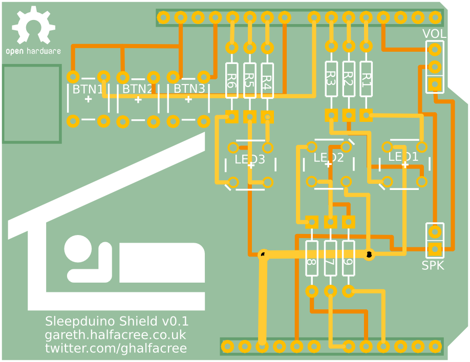
Sleepduino PCBAs a new father, I’ve found it’s difficult to convince my little bundle of noise to go to sleep at night. A common method of convincing a baby to sleep is to provide ‘white noise,’ either through the use of an expensive specialist baby-soother or by detuning a radio. Alternatively, there’s the Sleepduino.

Because I value my sleep more than I value my free time, I spent an afternoon designing and coding an combination white noise generator and nightlight for Alice’s nursery. Thankfully, I had the components I needed lying around: an Arduino with breadboard, three RGB LEDs, three tactile buttons, a piezoelectric buzzer and a potentiometer. Plus a whole mess of wiring.

The buttons control the LEDs: each LED has its own button, which cycles it through seven different colours before turning it off. Press the button again, and it’ll switch on again. The pot controls the volume of the buzzer, which exists to vocalise the output of a pseudorandom bit-shift register to generate a pleasing ‘static’ sound.

Set the LEDs to provide whatever level and colour of nightlight you think your baby – or, indeed, you – would prefer, adjust the volume of the white noise (apparently, it should be around the same volume as being in the same room as someone taking a shower) and cross your fingers that you’re going to enjoy the best night of sleep you’ve ever had.

It’s only the second proper night of using it, but it seems to be working: Alice had the best night’s sleep she’s ever had last night, and she’s been settled for a good couple of hours now without issue.

I’ve designed a printed circuit board version of the Sleepduino which plugs into the top of the Arduino without all the distracting and easily-knocked wiring. I’m making an initial prototype, which will arrive from the fab towards the end of the month. If it works, I’ll be opening the floor for anyone who wants to buy one.

Be aware, however: this is an Open Hardware project. I’m making the source code (most of which is appropriated from other projects anyway), schematics and PCB layout available under a Creative Commons Attribution-NonCommercial-ShareAlike licence, meaning you don’t have to buy one from me. If you’d rather, you can just grab the files and make one yourself. I won’t stop you. Hell, I’m actively encouraging it.

The pre-built shields will be for people who don’t fancy building one themselves, and I’ll probably also make them available with Arduino clones underneath so they’re literally ready to go out of the box.

Hopefully you guys will find them as useful as I’ve found the prototype version.

RetroGlove Pinout Diagram

So, I bought a PAX PowerGlove – so good it’s bad – with a view to connecting it to my PC for use as a neato peripheral. The PAX PowerGlove, hailing from Japan and predating the Mattel-manufactured US release, comes with a DB-15 Famicom peripheral connector.

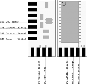
I need to figure out which of the 15 pins I need to connect to my USB adapter, but so far I’ve found four pinouts for the connector – and all four are different. Here’s my best-guess pinout:

Famicom Peripheral Connector1 – Ground
2 – Sound Out
3 – IRQ
4 – Port 1, Data 4
5 – Port 1, Data 3
6 – Port 1, Data 2
7 – Port 1, Data 1
8 – Port 1, Data 0
9 – Port 1, Data Clock
10 – Latch 2
11 – Latch 1
12 – Latch 0
13 – Port 0, Data 1
14 – Port 0, Clock
15 – +5V

In theory, that should be what I need to match up to my RetroGlove USB adapter:

RetroGlove Pinout Diagram

The only question is – have I picked the right Famicom pinout to trust, or will I blow my PowerGlove? Any suggestions, Famicom experts?

SEO Malware - Magzimus ThemeIf you Google my name at the moment, you’ll find some interesting results – and if you’ve hit this page as a result of looking for ‘webcam sex,’ you’re going to be disappointed.

I recently installed a new theme on the site – Magzimus – which I pulled from a site promising free WordPress themes. It’s pretty, it has a neat JavaScript slider, and it was a simple install.  What’s not to like?

Well, the fact that searching for my blog on various search engines now shows an affiliation with popular ‘adult entertainment’ site LiveJasmin, for a start.

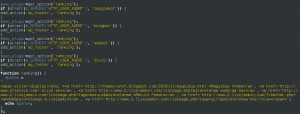
It seems that the ‘free’ theme has an interesting business model: a hidden bit of PHP code in the admin.php file that checks to see if traffic is coming from a search engine crawler, and if so adding a hidden span at the bottom of the page containing affiliate links to the aforementioned webcam site – and a variety of keywords that are likely to get me significantly different traffic to normal.

I’ve excised the code, and am now waiting for Google et al to update my listing and remove the spurious keywords.

Next time you snag a WordPress theme from somewhere, do what I failed to do: check the code to see exactly what it’s doing to your site.

A quick post containing photographic evidence of the state that Dyno-Rod left my house after a failed attempt to unblock my drains.  I wouldn’t have put them in public view, except for the fact that Dyno-Rod’s customer services e-mail has a size limit that means I can’t e-mail them. Yes, that’s human waste on the rug.

Arduino Duemilanove Side View

Arduino Duemilanove Side ViewJust a brief post to alert RSS subscribers that my how-to Arduino article is now live over on bit-tech.net.

Anyone who has ever hacked around in their PC will have been hit with an urge to take their tinkering to the next level and create a custom-built device, but few actually try – believing such things to be far too complicated. At least, until the Arduino appeared on the scene.

Originally developed in Italy in 2005 as a tool for students building interactive design projects, the Arduino is a microcontroller-based prototyping board – but one that pretty much removes the barriers to entry that previous electronic prototyping systems had.

The idea behind the Arduino is simple: to create a system that allows electronic circuits to be created, modified, and tested in minutes – complete with a programmable chip in the centre to take control of everything.

What are you still doing here? Go! GO!

Android Terminal Emulator running on a Milestone

Android Terminal Emulator running on a MilestoneRooting your Android smartphone can offer some pretty amazing benefits, from simple things like the ability to take screenshots to the option to use your handset as a Wi-Fi hotspot.  Perhaps the most impressive, however, is the option to change the apps that are pre-installed on your ‘phone, and replace them with your own.

In the case of my handset, a Motorola Milestone, app memory is at a premium: with just 196MiB of user-accessible storage on-board, larger apps can often mean having to remove something that’s already installed.  Thankfully, there’s a cheater’s way of freeing up some much-needed space: turn your optional apps into pre-installed versions.

First things first: you’re going to need a rooted handset.  If it’s not rooted, this tutorial will get you nowhere.  If you’re new to rooting, try the Easy Root Compatibility Test which offers certain ‘phones a one-stop solution.  If your handset isn’t supported, try one of the many guides on-line.

Once you’re rooted, you’re going to need a terminal emulator.  Install that, and you can get access to a shell – which is where the fun begins.

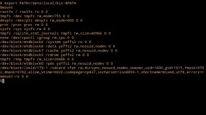
Step one – find out what’s mounted where with the command

 mount

You’ll see that we have a bunch of devices mounted in a bunch of locations, but the one we care about is /dev/mtdblock6, mounted as /system.  It’s in this special directory that Android stores all its internal gubbins – and to stop you from fiddling around with it, Google has very sensibly made it read-only.

Sadly, that also stops us from moving apps from the very limited user memory into the otherwise wasted system memory – and from deleting unwanted pre-installed apps, such as the Motorola-branded sat nav package that comes with the Milestone or the Facebook app that arrived unexpectedly as part of Android 2.1.

So, what can we do?  Easy: we re-mount the device as read-write.  You’ll need to become root using su, after which you can remount the block device.  Just type the following commands in to the terminal:

su -
mount -o remount,rw /dev/mdtblock6 /system

Now we have full read-write access to the /system file system. Bring up a directory listing of /system/app/ with:

ls -l /system/app/

You’ll notice that all the .apk files for the pre-installed apps are here.  Delete any .apk with rm and it’s gone for good – so for goodness’ sake be careful.

We can use the same command to take  a look at the .apk files for the apps we’ve got installed in user memory, too:

ls -l /data/app/

To move a package from user memory to system memory, making it ‘pre-installed’ and freeing up useful user memory, just do the following:

cp -f /data/app/com.publisher.packagename.apk

The file will be automatically removed from user memory and appear to vanish – but when you restart your ‘phone, it will re-appear as a pre-installed ‘system’ application.  Do this with a larger app, and you can free up a lot of valuable space.

A note about updating: because /system is mounted as read-only, the Android Market can’t write to it in order to update packages.  Instead, if an update for a pre-installed package is available, it will write the data back into user memory.  So, if you’ve saved 4MiB by moving Google Maps into /system, you’ll lose it all again the next time Google releases an update.

While it’s possible to get the space back – simply repeat the method of moving the file to /system again – it’s probably better to move applications that don’t get updated all that often.

That’s it: you can now enjoy significantly more space for apps!